Skip to main content


Geometric Dimensioning and Tolerancing (GD&T) is an essential system for defining and communicating design intent and engineering tolerances, pivotal in the manufacturing industry. It serves as a comprehensive language utilised by mechanical engineers, quality engineers, and professionals across various sectors to ensure precision and adherence to design specifications. GD&T training, offered by companies like GD&T Basics, caters to a wide range of audiences, including CNC machinists, engineering students, and design engineers, by providing diverse training formats like online courses and on-site training.
This training is crucial for minimising deviations, delays, and disputes in the manufacturing process, and it employs real-world examples and flexible training formats to enhance the learning experience. With resources available for both individuals and teams, GD&T training aims to equip participants with the skills necessary to effectively interpret and apply geometric tolerances and understand geometric tolerancing principles. As the demand for precise manufacturing continues to grow, mastering GD&T becomes pivotal for professionals in the manufacturing industry, ensuring that design intentions are accurately communicated and executed.
The Origins and Evolution of GD&T
The origins of Geometric Dimensioning and Tolerancing (GD&T) trace back to a critical period during World War II, aimed at addressing the inefficiencies of traditional X-Y area tolerancing. The innovative approach was developed by Stanley Parker in Great Britain, specifically at the Royal Torpedo Factory in Alexandria, Scotland, with the initial purpose of improving the inspection of torpedo parts. This led to the development of the position tolerance concept, significantly increasing the production of naval weapons by new contractors and improving the interchangeability of military parts.
Initial Development and Adoption:
- Developed during World War II by Stanley Parker
- Aimed to address limitations of traditional tolerancing methods
- First applied to improve torpedo part inspections
Standardisation and Global Acceptance:
- First standardized by the military in the 1950s
- Defined by ASME Y14.5-2018 for the USA and ISO 1101-2017 internationally
- Undergone multiple revisions, with ASME becoming the publisher in 2018
Impact on Manufacturing and Engineering:
- Increased production efficiency and part interchangeability during WWII
- Saves money and applies tolerances in a logical, standardized manner
- Not a fad, in existence for over 50 years, indicating its enduring relevance
This evolution from a wartime innovation to a globally recognized standard underscores the critical role of GD&T in modern manufacturing and engineering, ensuring precision, efficiency, and cost-effectiveness in the production process.
 Understanding the Basics of GD&T
At the core of GD&T is the concept of tolerance, which is essentially the permissible deviation from an ideal value that ensures the completed product functions correctly. This system standardises the measurement of product assembly variations, making it invaluable for maintaining quality in manufacturing processes.
Key Components of GD&T:
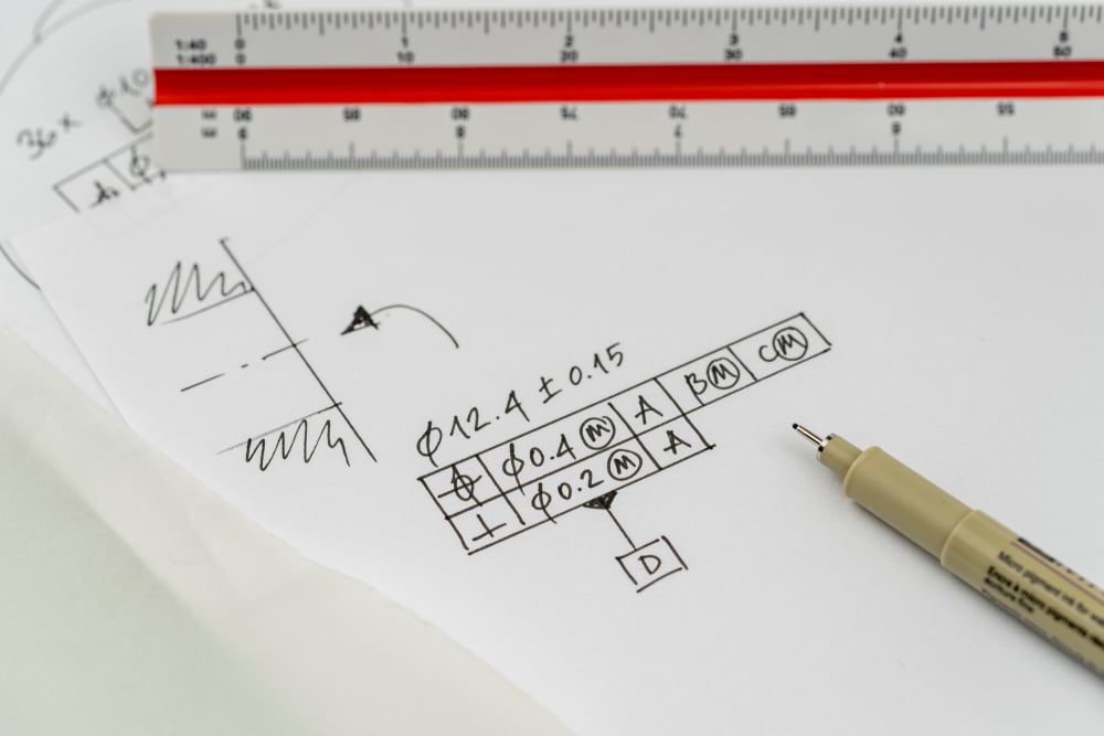
- Datums: Theoretically ideal lines, surfaces, or features serving as references for defining tolerance limits of other features
- Symbols and Controls: GD&T employs a comprehensive library of symbols to convey design intents, categorized into:
-
- Form Controls
- Profile Controls
- Orientation Controls
- Location Controls
- Runout Controls
These symbols are incorporated into the engineering drawings using the Feature Control Frame (FCF), specifying different controls for each feature to communicate the design intent effectively. Understanding these symbols and their correct application is crucial for the successful implementation of GD&T, as it not only communicates the nominal geometry but also the allowable variation in size, form, orientation, and location of individual features. This symbolic language enables clear communication between designers and manufacturers, reducing the likelihood of errors and misunderstandings that can arise from poorly designed drawings.
Key Elements of GD&T
In the realm of GD&T, the symbols and concepts play a pivotal role in ensuring manufacturing precision and efficiency. To navigate through the complexity of GD&T, it’s essential to understand its key elements:
GD&T Symbols and Groups:
- Form Controls: Ensure the shape of a feature is within the tolerance limit
- Profile Controls: Dictate the outline of a surface or feature, maintaining its form within specified limits
- Orientation Controls: Regulate the angle at which a feature or surface is laid out
- Location Controls: Define the exact placement of features in relation to the datums
- Runout Controls: Control the surface elements of a part to ensure they are within the tolerance when the part is rotated
Core Elements of GD&T:
-
- Size and Location: GD&T specifies the size and location, ensuring parts fit together correctly
- Form and Orientation: It controls the shape and orientation for precision
Datums and Feature Control Frames:
-
- Datums: Theoretical exact planes, points, or axes serving as reference points for other features
- Feature Control Frame (FCF): Indicates the geometric tolerance for part features, clearly defining the limits
Understanding these elements is crucial for mechanical engineers and quality engineers to implement GD&T effectively, enhancing the manufacturing process’s precision and efficiency.
 Applications and Advantages of Implementing GD&T
Implementing Geometric Dimensioning and Tolerancing (GD&T) brings numerous advantages across various stages of product development and manufacturing. By understanding its applications, industries can leverage GD&T for improved efficiency and product quality.
Enhanced Communication and Clarity:
- GD&T facilitates clear communication between design, manufacturing, and quality control teams, ensuring that everyone is on the same page regarding the product requirements 18. This is achieved through a standardized set of symbols and terms that describe the design intent rather than the resulting geometry itself 1.
Cost Savings and Manufacturing Flexibility:
-
- Statistical Process Control (SPC): GD&T enables SPC, significantly reducing product reject rates, assembly failures, and quality control efforts, leading to cost savings 1.
- Design for Manufacturing (DFM): Proper use of GD&T leads to faster time to market and improved DFM, allowing for maximum manufacturing flexibility 17.
- 3D Printing: In 3D printing, tighter tolerances controlled by GD&T can yield significant time and cost savings in prototyping and production, ensuring consistent running fits of mating parts 1.
Global Standardisation and Quality Improvement:
-
- Global Acceptance: As a globally accepted system, GD&T eliminates language barriers in overseas production, ensuring that vendors create precisely what the customer’s design requires
- Quality Control: GD&T provides clear instructions for quality control, with established rules for part setup and tolerance zone interpretation, allowing for additional (bonus) tolerances for increased part acceptance
These benefits underscore the importance of GD&T in achieving precision, efficiency, and cost-effectiveness in manufacturing, making it an indispensable tool in the engineering and manufacturing industry.
Challenges and Misconceptions
Despite its significant advantages, GD&T is not without its challenges and misconceptions, which can hinder its effective implementation:
- Misunderstandings and Misapplications:
- Mechanical designers often misinterpret or misapply GD&T, leading to costly errors, delays, and rework
- Misuse due to poor tolerancing on drawings can result in multiple interpretations, complicating the manufacturing process
- Training and Competency Issues:
- Proper training is crucial for effective GD&T usage. Inadequate training can lead to confusing and misinterpreted drawings
- It requires a significant investment in training to develop the necessary skills, but this can save time and reduce costs in the long run
- Perceived Barriers to Implementation:
- Some companies hesitate to use GD&T, fearing their suppliers won’t understand it. However, it’s essential to require suppliers to understand drawings to ensure quality
- GD&T is sometimes viewed as increasing part costs. In reality, when properly specified, it can offer larger tolerances that reduce manufacturing costs
Understanding these challenges and addressing the misconceptions are crucial steps towards leveraging GD&T’s full potential in the manufacturing industry.
Conclusion
Throughout this exploration of Geometric Dimensioning and Tolerancing (GD&T), it has been established that GD&T is not merely a set of rules but the backbone of precise manufacturing and quality assurance in engineering. By detailing its comprehensive symbols, standards, and applications, we have underscored its indispensable role in enhancing communication among teams, fostering cost efficiency, and ultimately leading to more reliable and accurately produced products. The historical context and evolution of GD&T pinpoints its enduring relevance, while the dive into its complexities illuminates the depth of understanding required to apply it effectively.
Facing the challenges and misconceptions around GD&T head-on, it’s clear that the pathway to mastering this intricate system lies in committed learning and professional development. With the significant advantages it offers—ranging from error reduction in the manufacturing process to the global standardization of production parameters—embracing GD&T becomes not just a strategic move but a necessary evolution for professionals in the field. For those ready to take their understanding of GD&T to the next level, it’s an opportune moment to book a demo and witness first-hand how its application can transform your projects. As the industry progresses, the mastery of GD&T will remain a vital skill, paving the way for more efficient, cost-effective, and high-quality manufacturing processes.
FAQ’s
What is the fundamental concept of Geometric Dimensioning and Tolerancing (GD&T)?
Geometric Dimensioning and Tolerancing, often abbreviated as GD&T or GD and T, is a systematic set of symbols and guidelines used by engineers and manufacturers. Its purpose is to precisely define a product’s geometry and dimensions, ensuring clear and consistent communication among those involved in the product manufacturing process.
What are the four core elements of GD&T?
The four core elements of GD&T are form tolerance, orientation tolerance, location tolerance, and run-out tolerance. These elements are essential for specifying the permissible variation in the shape and geometry of parts and components.
Can you list the five categories of GD&T symbols?
The five categories of GD&T symbols, as specified by the American Society of Mechanical Engineers (ASME), include form controls, profile controls, orientation controls, location controls, and runout controls. These categories cover the entire spectrum of geometric tolerances used in engineering and manufacturing.
What does rule 3 of GD&T entail?
Rule 3 of GD&T is known as “Regardless of Feature Size” (RFS). It is the standard condition applied to all geometric tolerances and does not require an explicit callout. RFS means that the geometric tolerances are applied to the feature of a part independently of its size dimensions, ensuring that the part’s geometry is controlled without considering how large or small the part is.